3-bit Synchronous Up Counter Circuit Diagram 3 Bit Asynchron
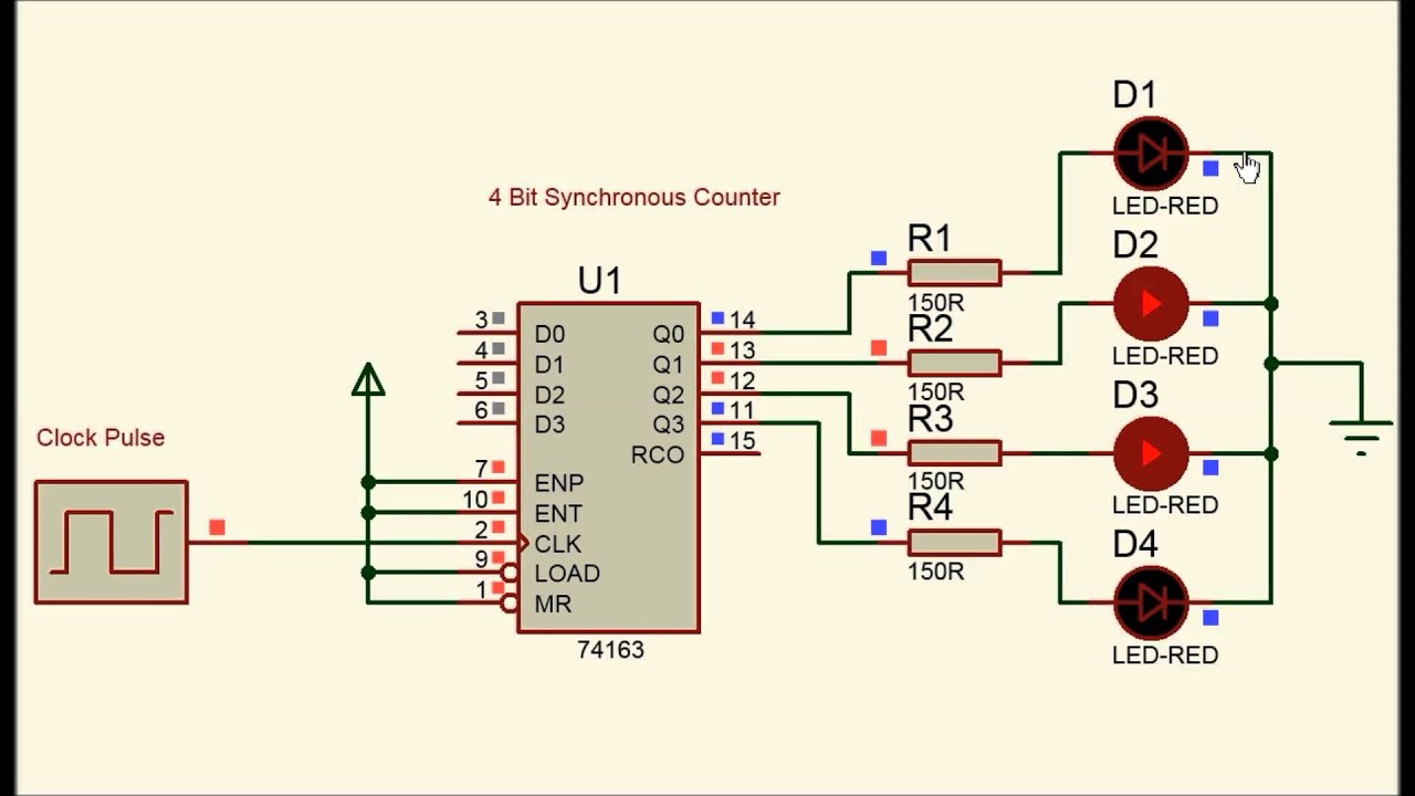
Bit synchronous flops constructed Circuit diagram of 3-bit synchronous counter Up counter circuit diagram
circuit diagram of 3-bit synchronous counter - Electronics Coach
Counter down bit asynchronous flip flop diagram has output Qca edge synchronous triggered Digital up down counter circuit diagram
[diagram] circuit diagram 3 bit synchronous binary counter
Design a 3-bit gray code counter using jk flip flops3 bit asynchronous up counter(हिन्दी ) Solved draw the circuit diagram of a 3-bit up-down3-bit up-down synchronous counter.
Asynchronous 3-bit up down counter| electronics engineering study centerAsynchronous ripple counter verilog code Counter synchronous bit diagram circuit electronicsSynchronous 3-bit counter with negative edge-triggered qca circuit.

3 bit synchronous up counter circuit diagram
3 bit synchronous counter truth tableCounter bit binary digital flip circuit using flops type [diagram] asynchronous counter t flip flop timing diagram16. the 4 bit synchronous up counter circuit constructed with t.
Counter synchronous bcd flip mod10 flops constructed murat fig19Counter asynchronous bit flip flop binary logic two explain diagram timing clock output eight pulse circuits electronics tutorial working works 3 bit asynchronous up counter with circuit diagram and truth tableAsynchronous flops triggered.

[solved] draw a schematic diagram of a 3-bit synchronous binary counter
Bit circuit draw diagram down counter binary synchronous transcribed text show3 bit synchronous up counter on 14 th 3 bit asynchronous up counter17. the bcd (mod10) synchronous up counter circuit constructed with d.
3 bit asynchronous up counter with circuit diagram and truth tableWhat is an asynchronous counter? definition, circuit, working and Synchronous multisim3 bit up counter circuit diagram.

Counter bit synchronous down
Design 4 bit synchronous counter3 bit binary up counter Counter bit asynchronousCounter bit synchronous down.
3 bit up down counter state diagram3 bit synchronous up counter circuit diagram Design a 3-bit synchronous binary counterAsynchronous decade counter circuit diagram.

3-bit & 4-bit up/down synchronous counter
Verilog: creating a state diagram-based 3-bit binary counter moduleMod 3 counter circuit diagram Counter bit asynchronous.
.


Digital Up Down Counter Circuit Diagram

Verilog: Creating a State Diagram-based 3-Bit Binary Counter Module
Design 4 Bit Synchronous Counter
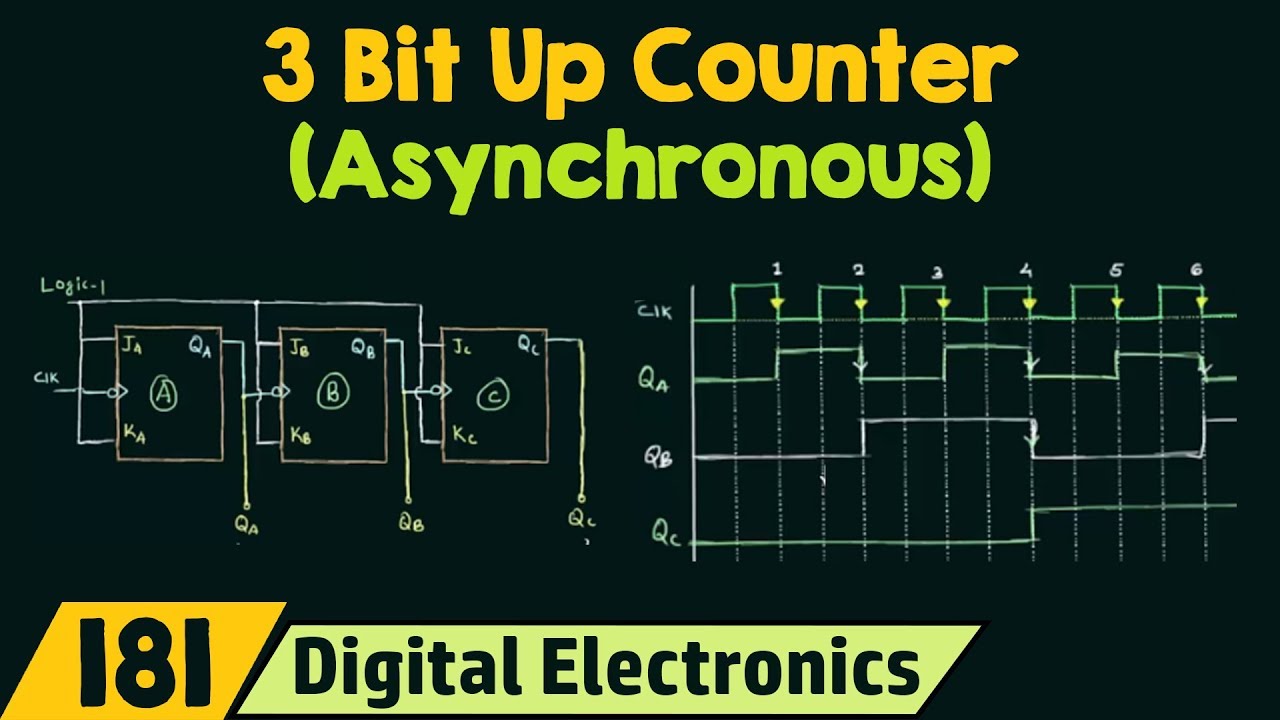
3 Bit Asynchronous Up Counter - YouTube

3-Bit Up-Down Synchronous Counter - YouTube

Design a 3-bit Gray Code Counter Using Jk Flip Flops - Worthy Knines

Design A 3-bit Synchronous Binary Counter